 Skip to content

How to Design Plastic Parts for Injection Molding?
Designing a plastic part for injection molding begins long before resin reaches the machine. The shape must perform reliably, fill evenly, cool predictably, and release without damage. Robert A. Malloy, author of Plastic Part Design for Injection Molding, offers a useful principle, paraphrased here: “Design the part for its function and for the process that will make it.” It sounds simple. It isn’t. A thick boss beside a thin wall, for example, can cool slowly and leave a visible sink mark. A sharp internal corner can concentrate stress. Small choices matter.
This outline introduces practical plastic component design decisions, from material selection and wall thickness to draft angles, ribs, and gate placement. It also explains how part geometry affects tooling, cycle time, appearance, and cost. Picture a thin-walled enclosure with a snap-fit lid: its tabs need enough flexibility, while nearby walls must remain stiff. That balance takes careful review. Design rules help, but they cannot replace testing. Resin grades behave differently, and mold conditions can expose weaknesses that drawings do not show. A prototype may still warp. A polished surface may reveal flow lines. These are useful warnings, not reasons to ignore sound design practice. The sections ahead provide a clear framework for reducing avoidable defects and making better-informed decisions with molders and engineers.
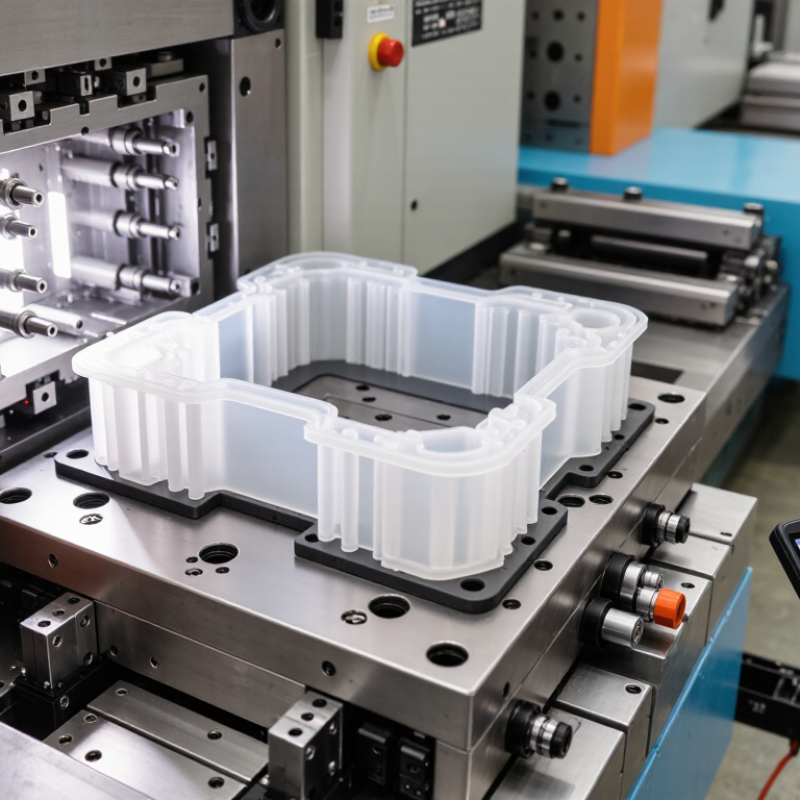
Select Resin and Set Tolerances Using Supplier Data and ISO 20457
Resin choice sets the limits for a molded part. Compare supplier data for shrinkage, moisture absorption, flow, and recommended processing temperatures. A glass-filled resin may shrink less along the fiber direction, yet behave differently across it. That can shift a clip or mounting hole away from its intended position. Check data for the exact grade, not just the polymer family.
Use ISO 20457 as a framework for specifying tolerances on molded plastic parts. It helps connect tolerance requirements with material and manufacturing conditions, but it does not replace a conversation with the molder. Identify critical dimensions, such as a bearing seat or snap-fit gap, and mark less important surfaces with broader limits. Ask the supplier what variation is realistic for the selected resin, wall thickness, and tool design. Measure parts under agreed conditions; temperature and moisture can affect results.
Be practical. Tight tolerances can raise tooling and inspection demands without improving how an assembly works. A nominal hole size may look precise on a drawing, but resin shrinkage and part geometry matter too. Review sample parts, compare measurements with supplier capability data, and adjust the drawing before production. The first estimate may be wrong. That is useful feedback, not a failure.
How to Design Plastic Parts for Injection Molding? - Select Resin and Set Tolerances Using Supplier Data and ISO 20457
| Resin family | Typical molding shrinkage* | Design considerations | Tolerance-setting approach | Supplier data to confirm |
|---|---|---|---|---|
| ABS, unfilled | Approximately 0.4–0.7% | Often selected for impact resistance and surface finish. Keep wall thickness reasonably uniform to reduce sink and warpage. | Use ISO 20457 to select the applicable tolerance group and assess each dimension by its size and function. Treat the drawing tolerance as a design requirement, not a guaranteed process capability. | Grade-specific shrinkage, flow direction effects, recommended processing window, and demonstrated capability for critical dimensions. |
| Polycarbonate (PC), unfilled | Approximately 0.5–0.7% | Useful where toughness and impact performance are important. Consider stress concentrations, chemical exposure, and the effect of molding stresses. | Apply ISO 20457 tolerance guidance to the part’s nominal dimensions and functional needs. Allow wider tolerances for non-critical features where assembly permits. | Grade-specific shrinkage, drying requirements, allowable molding conditions, and dimensional capability after conditioning. |
| Polypropylene (PP), unfilled | Approximately 1.0–2.5% | Shrinkage and warpage can vary with geometry and flow. Rib, boss, and wall design should limit local thick sections. | Do not derive tool dimensions from a single generic shrinkage value. Agree on the resin grade, tool-steel compensation, and tolerance plan with the molder. | Grade- and process-specific shrinkage, flow/transverse behavior, and warpage data for the intended part geometry. |
| Polyamide 6 (PA6), unfilled | Approximately 0.7–1.5% | Moisture absorption can change dimensions and mechanical properties. Define the condition in which dimensions are measured. | Set tolerances around the functional condition, including any specified moisture conditioning. Use ISO 20457 as the tolerance framework and document inspection conditions. | Conditioned and dry-state dimensional data, moisture-conditioning guidance, grade-specific shrinkage, and capability evidence. |
| Polyoxymethylene (POM), unfilled | Approximately 1.8–2.5% | Good dimensional behavior in many applications, but the relatively high molding shrinkage must be considered in tool design. | Identify critical mating and functional dimensions first. Agree on the ISO 20457 tolerance group and verify achievable tolerances through mold trials. | Grade-specific shrinkage, dimensional stability data, processing conditions, and measured capability for critical features. |
| Polybutylene terephthalate (PBT), glass-filled | Often approximately 0.3–0.8%; varies with glass content and flow direction | Fiber orientation can cause directional shrinkage and warpage. Gate location and flow path can strongly affect dimensions. | Review dimensions in both flow and transverse directions. Use ISO 20457 with the supplier’s directional data; confirm critical dimensions on molded samples. | Exact glass content, directional shrinkage, fiber-orientation effects, moisture and conditioning data, and process capability. |
*Shrinkage figures are indicative ranges, not guaranteed material specifications. Actual values depend on the exact resin grade, part geometry, mold design, flow direction, and processing conditions. Obtain the current supplier data sheet and agree on measurement conditions before finalizing tool dimensions and drawing tolerances. ISO 20457 provides a framework for specifying tolerances for injection-molded plastic parts; the applicable tolerance group should be selected for the part and verified with the molding supplier.
Related Posts
-

2026 Top Trends in Plastic Part Manufacturing for Innovative Industries
-
China Top Plastic Injection Molding Manufacturers?
-
How to Create Effective Plastic Product Design for Everyday Use?
-

How to Choose Eco Friendly Packaging for Your Business?
-

Top Plastic Product Innovation Trends for Global Buyers?
-

Why Choose Plastic Assembly Solutions for Global Buyers?