How to Design a Plastic Mold for Manufacturing
Designing a plastic mold is not just a matter of shaping a cavity. It is a practical engineering process that connects part geometry, material behavior, machine limits, and production goals. A thoughtful plastic mold design can help produce consistent parts, reduce defects, and avoid costly changes after tooling begins. Small decisions matter. A sharp internal corner, uneven wall, or misplaced gate may affect filling, cooling, and part removal.
This guide introduces the choices that shape a manufacturable mold, from reviewing the component and selecting a suitable resin to planning the parting line, draft angles, gates, cooling channels, and ejector pins. For example, a rib that is too thick may create a visible sink mark, while poorly balanced cooling can leave one side of a part warmer than the other. These details deserve attention before steel is cut. They are easier to adjust on a drawing.
There is no single layout that works for every part. Mold complexity, expected production volume, surface requirements, and available equipment all influence the design. A checklist can help, but it cannot replace careful review of the actual geometry. That assumption deserves a second look. Early feedback from experienced mold designers and manufacturing teams can reveal risks that a screen model may hide. The goal is not a perfect first draft; it is a design that can be tested, refined, and produced reliably.
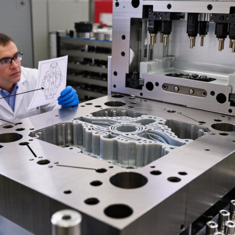
Define the Part Geometry and Production Requirements
How to Design a Plastic Mold for Manufacturing
Define the Part Geometry and Production Requirements
Begin with the part, not the mold. Define its function, assembly points, load areas, and visible surfaces. Record material, annual volume, target cycle time, dimensional tolerances, and expected service temperature. The Plastics Industry Association reported $548.1 billion in U.S. plastics shipments and 1.55 million jobs in its 2023 Size and Impact Report. That scale makes repeatable design decisions essential.
Map wall thickness before adding ribs or bosses. Keep transitions gradual, because abrupt changes can create sink marks, voids, or warpage. Add draft to vertical faces, and confirm ejection direction early. A 1-degree draft may work for many surfaces, but textured or deep features often need more. Check the resin supplier’s shrinkage range, not a generic chart. It can change with flow direction and packing pressure.
Specify the parting line, gate location, vents, cooling channels, and ejection zones together. ISO 20457 provides a useful framework for molded-part tolerances and acceptance conditions. For high-volume programs, production data deserves equal attention. The same industry report shows why a small cycle-time loss can become expensive across millions of parts. Validate fill, cooling, and warpage with simulation, but question the model. It is not reality.
A first geometry pass is rarely correct. Test critical dimensions with prototypes, then revise the mold concept before steel is cut. Some features will still be too optimistic. That is normal.
Define Part Geometry and Production Requirements
Example design inputs for an injection-molded polypropylene enclosure planned for 50,000 units per year, with a target dimensional tolerance of ±0.2 mm. The chart shows illustrative nominal wall thicknesses in millimeters; actual values should be validated for the part geometry, resin, tooling, and production process. Keeping wall thicknesses reasonably uniform can help reduce sink marks and warpage.
Select the Plastic Resin and Molding Process
Choose the resin and molding process together. The resin determines how a part handles heat, impact, chemicals, and repeated loading. The process affects wall thickness, surface finish, production speed, and tooling cost. A housing near a warm motor, for example, may need better heat resistance than a decorative cover. Small details matter.
Compare the part’s requirements with candidate resins before shaping the mold. Polypropylene is often chosen for flexible, lightweight components, while ABS can suit rigid housings that need a smooth finish. These are starting points, not guarantees; grade and part geometry change performance. Ask suppliers for data on shrinkage, flow, and moisture sensitivity. Some resins need careful drying before molding, or defects may appear as streaks or bubbles.
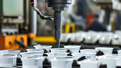
Injection molding works well for detailed parts and repeat production, but its mold must account for flow, cooling, and ejection. Blow molding is better suited to hollow containers, while thermoforming can fit larger, thinner panels. The cheapest process on paper may create awkward tooling or slow cycles. I would test a small prototype before locking in the mold design. It can reveal a stubborn sink mark, a weak snap-fit, or a draft angle that looked fine in CAD. That extra check may feel inconvenient, but reworking steel later is usually harder.
Design the Mold Cavity, Core, and Parting Line
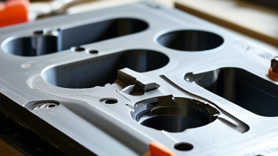
The cavity forms the part’s outer surfaces, while the core shapes its internal features. Their geometry must match the intended wall thickness, not just the finished outline. Uneven sections can cool at different rates and cause sink marks or warpage. Small details matter. Add draft to walls so the part can release without scuffing; the required angle depends on depth, texture, and material. Confirm shrinkage values with material data and molding trials rather than relying on a generic estimate.
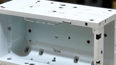
The parting line is where the mold halves meet. Place it along a natural edge or contour when possible, keeping visible witness marks away from cosmetic faces and sealing surfaces. It does not have to be flat. A stepped line may fit the part better, but it can make machining and alignment harder. Check that shutoffs are accessible and robust, and leave room for vents near areas where air may become trapped.
Review the core and cavity together with gates, ejector pins, and cooling channels. Ejector pins should push on sturdy, preferably hidden areas; otherwise, they can leave marks or distort a thin wall. A practical design may involve trade-offs. Moving the parting line can improve appearance but complicate tool construction. That choice is rarely perfect. Document the reasoning and revisit it after a mold-flow review or prototype inspection.
Validate the Design and Prepare the Mold for Production
Validate the mold design before committing to production. Review the parting line, draft angles, wall thickness, and gate location against the actual part geometry. Run a mold-flow analysis to check for air traps, weld lines, and uneven filling. Treat the results as useful evidence, not a guarantee. A first trial can look convincing while hiding sink marks or warpage that appear after cooling.
During a tool trial, record melt temperature, injection pressure, cooling time, and part dimensions. Inspect several consecutive shots, not just the best-looking sample. Check critical features with suitable gauges, and compare results with the drawing tolerances. If dimensions drift, adjust the process or revisit the mold; do not assume operators can compensate indefinitely. Some details may still need refinement. Document approved settings, inspection criteria, and maintenance points before handoff. Confirm that vents are clean, cooling channels flow properly, and moving components operate smoothly.
Tips: Keep labeled trial samples and their process notes together. Use a checklist for final inspection, and leave room for one more review. Small oversights happen. Catch them before the production schedule gets tight.
How to Design a Plastic Mold for Manufacturing — Validate the Design and Prepare the Mold for Production
| Validation Area |
Design or Process Check |
Acceptance Criterion |
Example Validation Result |
Production Readiness |
| Part geometry |
Review nominal wall thickness and transitions in the molded part. |
Wall thickness follows the part-specific design specification; abrupt thickness changes and unnecessary material buildup are addressed. |
Nominal wall: 2.0 mm; measured review range: 1.9–2.1 mm. No unapproved thick sections identified. |
Pass |
| Draft and part release |
Check draft angles, shutoffs, and the proposed direction of mold opening. |
Draft is sufficient for the surface finish and material; undercuts have an approved release mechanism. |
Side walls: 1.0° draft; textured faces: 2.0° draft; side actions included for two confirmed undercuts. |
Pass |
| Gate and runner layout |
Review gate location, runner balance, weld-line position, and expected filling pattern. |
Filling analysis shows acceptable flow balance, with critical weld lines and gate vestiges kept away from restricted areas. |
Simulated cavity fill-time difference: 4%; weld lines located outside the defined load-bearing region. |
Pass |
| Venting |
Inspect vent locations at end-of-fill areas and around trapped-air risks. |
Vents are included where required and sized for the selected resin and mold design; no burn marks or trapped-air defects occur during trials. |
Vents added at end-of-fill locations; first-off trial showed no visible burn marks. |
Pass |
| Cooling system |
Check cooling-channel layout, accessibility, and circuit flow. |
Circuits are documented and provide stable, repeatable cooling without leaks; part temperature and cycle time meet the approved process plan. |
All circuits passed a 10-minute leak check at 0.6 MPa; measured flow ranged from 8.1 to 8.5 L/min per circuit. |
Pass |
| Dimensional verification |
Measure critical-to-quality features on parts molded under a stable process. |
Dimensions meet the approved drawing tolerances; capability target is defined for the feature and measurement plan. |
30 consecutive parts measured; critical bore: 10.02 mm average against a 10.00 ± 0.10 mm tolerance; Cpk: 1.42. |
Pass |
| Process window |
Record the approved material, drying conditions, melt temperature, mold temperature, and injection settings. |
Settings stay within the resin supplier’s guidance and the validated process window; the approved setup is recorded for repeat runs. |
Resin drying: 80°C for 4 hours; melt temperature: 230°C; mold temperature: 40°C; settings recorded in the trial sheet. |
Pass |
| Tooling and production release |
Confirm mold identification, maintenance instructions, spare components, and approved sample sign-off. |
Tool documentation is complete, open issues are closed or formally accepted, and the designated reviewer approves production release. |
Tool checklist and maintenance plan complete; approved samples signed off; no open critical issues. |
Ready for release |
Example validation record for planning purposes. Confirm acceptance limits, resin processing conditions, and capability requirements against the approved part drawing, material data, and quality plan.
 Skip to content