
Skip to content

What Is a Wire Winder and How Does It Work?

A Wire Winder is a machine or hand-operated tool that coils wire onto a spool, reel, or custom frame. It controls tension, speed, and alignment during winding. Without those controls, wire can overlap, kink, or slip from the reel.

These systems appear in cable production, electrical workshops, manufacturing plants, and repair facilities. A typical unit includes a rotating shaft, tensioning device, guide arm, and drive motor. The shaft turns the spool. The guide moves across its width. Together, they create even layers instead of a tangled bundle. Some models use sensors to measure length or detect uneven winding.

Understanding how a Wire Winder works helps users choose suitable equipment. Copper wire, steel wire, insulated cable, and fine magnet wire may require different settings. Thickness matters. So does flexibility. A technician may adjust the winding speed while checking the coil’s edges by hand. Small changes can prevent damaged insulation and unstable reels.

The process sounds simple. It is not always simple.

Real performance depends on spool size, wire tension, operator skill, and machine condition. Manufacturers often provide technical specifications, but practical testing remains important. A reliable setup should produce firm, clean coils without crushing the wire. Operators should also inspect guards, emergency stops, and moving parts before use. This article explains the main components, working process, common applications, and selection factors behind Wire Winder equipment. It also considers limitations that product descriptions sometimes overlook.
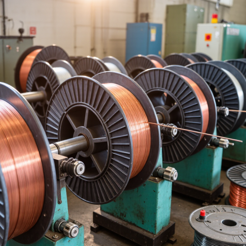
What Is a Wire Winder and How Does It Work?

What Is a Wire Winder and What Purpose Does It Serve?

A wire winder is a machine that coils wire onto a spool, reel, or custom core. Its main purpose is to keep long wire neat, protected, and ready for storage, transport, or later processing. Without controlled winding, wire can form knots, sharp bends, or overlapping loops. Those problems may slow production and damage insulation.

The machine usually uses a rotating spindle, a tension device, and a moving guide. The spindle turns the spool while the guide places each layer across its width. Adjustable tension keeps the wire firm without stretching or crushing it. Some models use sensors to measure length, detect breaks, or stop when the spool is full. The correct winding pattern depends on wire thickness, flexibility, and the spool design.

In workshop use, operators often check the first few layers by hand. Small errors there can affect the entire coil. A wire winder is useful for electrical assembly, cable preparation, repair work, and organized inventory. It improves consistency and reduces manual handling. However, it is not foolproof. Excessive tension may weaken delicate wire, while loose tension can create unstable coils. Settings should be tested with the actual wire, not guessed from a chart. The process still requires judgment.

Key Components and Design of a Wire Winder

A wire winder is built around a simple task: placing wire onto a spool in controlled, even layers. Its frame supports the spool shaft, drive unit, and guiding assembly. The shaft must remain rigid under load, because slight runout can create loose edges or crossed turns. Many working designs use bearings at both ends. They reduce friction and keep rotation stable. The spool itself may be removable, allowing faster changeovers. This sounds straightforward. It is not always forgiving.

The drive system usually combines an electric motor, gearbox, and speed controller. Together, these parts determine winding speed and starting torque. A tensioner keeps the wire firm without crushing insulation or stretching the conductor. It may use a dancer arm, friction disc, or pneumatic mechanism. The traverse guide moves side to side as the spool turns. Its travel rate must match spool speed and wire diameter. If the guide moves too quickly, gaps appear. If it moves too slowly, layers pile up near one flange.

Reliable machines also include sensors and a practical control system. A rotation sensor can monitor shaft speed, while a tension sensor detects sudden changes in pull. The controller then adjusts motor output or pauses the cycle. Guards cover rotating parts, and an emergency stop should be easy to reach. In field use, calibration matters as much as component quality. Dust, temperature, and changing wire batches can alter tension. Operators should inspect guide surfaces, bearings, and spool alignment before production. A perfect setting rarely stays perfect. Thoughtful adjustment still matters.

How a Wire Winder Operates Step by Step

What Is a Wire Winder and How Does It Work?

A wire winder is a machine that coils wire onto a spool or reel. Its job is controlled movement, steady tension, and even layering. The process starts when an operator loads an empty spool onto the rotating shaft. The wire passes through guide rollers before reaching the spool. These rollers remove twists and keep the wire moving smoothly. Keep it centered.

When the motor turns the spool, the wire begins wrapping around its surface. A tension arm or sensor measures the pulling force during winding. If tension drops, the system adjusts the motor speed or guide position. If tension rises, it reduces the pull to protect the wire. A traverse guide moves from side to side across the spool. This repeated motion lays each turn beside the previous one. Poor alignment creates gaps, overlaps, or damaged insulation.

As winding continues, sensors can detect the spool’s rotation and wire position. At the target length, the machine slows before stopping. The operator then secures the wire and removes the filled spool carefully. A close inspection checks loose turns, uneven edges, and surface damage. In practice, no setting is perfect for every wire type. Small corrections often prevent larger problems. A slightly lower speed may improve winding quality, especially with thin or flexible wire.

What Is a Wire Winder and How Does It Work? - How a Wire Winder Operates Step by Step

A wire winder is a machine that places wire or cable onto a spool, reel, coil, or other carrier in controlled layers. It coordinates rotation, wire tension, traverse movement, and length measurement to produce a compact and consistent winding pattern.

Wire Winder Operating Sequence and Typical Technical Data
Step Operating Stage What Happens Main Components Involved Typical Data or Control Point Result or Quality Check
1 Prepare the Empty Spool The empty spool is mounted on the winding shaft and secured so that it rotates concentrically without excessive runout. Winding shaft, chuck, collet, spool supports, locking mechanism Spool core diameter: commonly about 50–500 mm, depending on the application. The spool is centered, firmly clamped, and suitable for the wire size and finished coil weight.
2 Load and Align the Wire The wire is fed from a payoff reel or supply container through the prescribed path toward the spool. Payoff reel, guide rollers, ceramic or polymer guides, alignment sensors Wire diameter: may range from fine wire below 0.1 mm to several millimetres in general winding applications. The wire path is straight, unobstructed, and free from sharp contact points that could damage insulation or the conductor.
3 Set the Winding Direction The control system selects clockwise or counterclockwise rotation according to the required coil orientation and lead position. Drive motor, motor controller, programmable control system Rotation direction: selected before starting; direction changes are normally made only when the machine is stopped or under controlled conditions. The first wire lead is positioned at the specified starting location on the spool.
4 Apply Initial Tension A controlled pulling force removes slack and keeps the wire seated against the spool without overstressing it. Tensioner, dancer arm, load cell, magnetic or mechanical brake Tension setting: selected according to conductor size, insulation type, tensile strength, and allowable elongation. The wire remains stable during acceleration and does not visibly stretch, kink, buckle, or slip.
5 Start Spool Rotation The winding shaft accelerates smoothly to the programmed speed while the controller monitors tension and position. Electric motor, drive controller, encoder, emergency-stop circuit Speed control: commonly adjusted from low-speed positioning to several hundred revolutions per minute; the safe limit depends on spool diameter, wire mass, and machine design. Acceleration is smooth, with no sudden tension spike, wire whip, or spool movement.
6 Traverse the Wire Guide A guide moves laterally across the spool face so each turn is placed beside the previous turn rather than randomly piling up. Traverse carriage, lead screw, linear actuator, guide nozzle, position sensor Traverse pitch: typically set close to the effective wire diameter for orderly adjacent winding; special patterns may use a different pitch. The wire forms a uniform layer with consistent spacing and limited crossover.
7 Build Each Layer When the guide reaches one flange, it reverses direction or follows the programmed pattern to create the next layer. Traverse controller, limit sensors, spool flanges, position feedback system Layer count: determined by the usable spool width, wire diameter, and required wire length or coil height. Layers remain within the spool flanges and maintain an even, compact profile.
8 Measure Wire Length The machine estimates or measures the amount of wire wound by using encoder feedback, a measuring wheel, or both. Rotary encoder, measuring wheel, length counter, control software Length calculation: based on measured feed movement or spool rotation combined with the effective winding diameter. The target length is reached without relying solely on visual estimation.
9 Control Speed and Tension Continuously As the coil diameter increases, the controller adjusts rotational speed and braking so the linear wire speed and tension remain within the selected limits. Feedback controller, tension sensor, encoder, motor drive, brake Control objective: stable tension and consistent deposition throughout the changing coil diameter. The finished coil has consistent density, minimal loose loops, and no crushed or damaged insulation.
10 Stop at the Target The machine decelerates when the programmed length, layer count, diameter, or weight is reached. Controller, length sensor, diameter sensor, motor brake Stop condition: may be length-based, diameter-based, layer-based, weight-based, or a combination of these. The wire end is accessible and the coil remains secure without unraveling.
11 Secure and Cut the Wire The wire is held against the spool or secured with tape, a clip, a tie, or a designated terminal before being cut. Wire clamp, cutter, end-holder, labeling or marking device Cutting method: selected according to wire material, diameter, insulation, and required end condition. The cut end is clean, identified if necessary, and protected from unwinding or conductor damage.
12 Inspect and Remove the Finished Coil The operator checks the winding appearance and removes the completed spool from the shaft for packaging or the next production operation. Operator inspection tools, diameter gauge, weighing scale, spool-release mechanism Inspection points: coil width, outer diameter, wire length, tension uniformity, end security, and visible surface damage. The spool is ready for storage, transport, assembly, electrical testing, or further processing.

Note: Operating values vary with wire material, conductor diameter, insulation, spool geometry, required winding pattern, and machine construction. The ranges shown are general engineering references rather than fixed settings for every wire-winding application.

Common Types and Applications of Wire Winders

A wire winder is a machine that guides and coils wire around a reel, bobbin, or core. Its controller manages tension, speed, and layer spacing. A sensor can stop the machine when the wire breaks or reaches a preset length.

The working detail is simple, but poor tension creates loose loops, crushed insulation, and uneven coils.

Common Types and Applications

Common types include traverse winders, precision winders, toroidal winders, and take-up winders.

Traverse winders move a guide from side to side, making neat coils for cables and magnet wire.

Toroidal winders wrap wire around ring-shaped cores used in transformers and filters.

Take-up winders collect finished cable after extrusion.

These machines support motor production, electrical components, renewable-energy equipment, and communication cables. The International Energy Agency’s 2023 Electricity Grids and Secure Energy Transitions report says more than 80 million kilometres of grids must be added or refurbished globally by 2040. That demand increases pressure for reliable cable processing, although winding is only one part of the supply chain.

Tips

Match the winder to wire diameter, insulation type, and coil geometry.

Check tension with a calibrated gauge, not by touch alone.

Keep the guide clean; a small fragment can shift every layer.

Record speed, tension, and defect rates during each batch.

A slower setting may improve consistency, but not always.

Operators should test a sample coil before full production, because theoretical settings often fail on real materials.

Factors to Consider When Choosing a Wire Winder

A wire winder guides and coils wire onto a spool with controlled tension and rotation. Its motor turns the spool while a traversing guide distributes each layer evenly. This process reduces tangles, damaged insulation, and uneven coils during production or repair work. The machine looks simple, but small settings matter.

Start with the wire’s material, diameter, flexibility, and surface coating. A winder designed for thin copper wire may struggle with stiff cable. Check the acceptable wire range carefully. Tension control is equally important. Excessive tension can stretch conductors or deform insulation, while low tension creates loose layers. Adjustable speed helps operators match the winding rate to the wire. Faster is not always better. In practical workshop checks, a slower setting often produces cleaner edges.

Spool size and winding width must match the intended job. Measure both before choosing equipment. A programmable traverse system can maintain consistent spacing, especially on narrow spools. Look for readable controls, emergency stopping, guarding, and stable mounting. These features support safer, repeatable operation. Maintenance access also deserves attention. Dust around guides and bearings can affect alignment over time. I would test the winder with the actual wire, not only the advertised specifications. A short trial can reveal vibration, slipping, or poor layer formation. Documentation should explain calibration and replacement parts clearly. Even experienced operators can overlook compatibility details.

Article Source:

Scroll To Top