Skip to content

Why Choose a Module Transceiver for Global Networking?

Global networks are no longer built around one location, one vendor, or one traffic pattern. They connect cloud regions, data centers, mobile sites, campuses, and remote branches across changing distances. Cisco’s Annual Internet Report forecast 5.3 billion internet users and 29.3 billion connected devices by 2023. That scale makes adaptable optical connectivity a practical requirement, not a luxury.

A Module Transceiver allows network operators to match interface speed, fiber type, wavelength, and transmission distance with specific deployment needs. In a regional data center, a 100G module may connect racks through short multimode fiber. A long-haul 400G coherent module may serve a different route entirely. Operators can replace the interface without redesigning the complete switch or router. This supports phased upgrades and can reduce equipment waste. The details matter. Engineers must verify form factor, power consumption, operating temperature, digital diagnostics, and equipment compatibility. A module that works in a laboratory may behave differently inside a crowded rack.

Industry evidence supports this flexible approach. The ITU’s Facts and Figures 2023 reported that 5.4 billion people were online, while billions remained unconnected. Meanwhile, the Omdia Optical Network Hardware and Components market research tracks continuing demand for higher-capacity optical components across data center and telecom networks. These reports indicate sustained pressure, but they do not make every module a perfect choice. That assumption is too simple. Vendor coding, firmware support, connector quality, and real-world thermal conditions can still create costly surprises. Careful testing remains essential. A reliable global network depends on both modular hardware and disciplined engineering decisions.
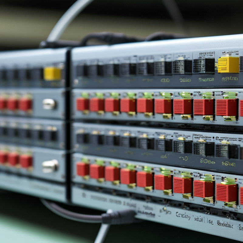
Why Choose a Module Transceiver for Global Networking?

Module Transceivers: Definition and Role in Global Networking

Why Choose a Module Transceiver for Global Networking?

A module transceiver is a compact, pluggable device that sends and receives network signals. It converts electrical data into optical signals, or the reverse. This process connects switches, routers, servers, and transmission equipment across different network environments. Modules may support copper links, single-mode fiber, or multimode fiber. Their specifications include data rate, wavelength, reach, connector type, and operating temperature.

That flexibility matters in global networking. A regional data center may need short connections, while an undersea landing station requires long-distance optical transmission. Engineers can select modules for each link instead of replacing entire systems. This reduces installation disruption and simplifies future upgrades. Diagnostic features can report temperature, voltage, and optical power. These readings help technicians identify a weak fiber, poor connection, or failing module before service becomes unstable.

Compatibility still requires careful checking. A module can fit physically but fail through incompatible standards, coding, power limits, or fiber characteristics. Small details matter. Field testing should include link loss, bit error performance, and connector cleanliness. Dust is easy to overlook. So are temperature changes inside crowded racks. Reliable planning also includes spare units and documented settings, although real projects rarely remain perfectly organized. A module transceiver is not a universal solution. Its value depends on accurate specifications, disciplined installation, and continuous monitoring across every network segment.

Key Technologies Behind Module Transceiver Connectivity

Why Choose a Module Transceiver for Global Networking?

Key Technologies Behind Module Transceiver Connectivity

Module transceivers support global networking by combining signal conversion, optical transmission, and compact installation. They connect switches, routers, servers, and long-distance fiber links. Their modular design allows technicians to replace one communication unit without changing an entire network device. That reduces service disruption during planned maintenance. It also helps organizations adapt as bandwidth requirements change.

Several technologies determine their real performance. Digital signal processing can correct distortion caused by distance, interference, and imperfect components. Forward error correction adds recovery data, helping receivers rebuild damaged information. Wavelength control enables multiple channels to share one fiber while maintaining separation. Thermal management is equally important. A small module may operate beside many heat-producing components. Without careful temperature control, signal quality and service life can decline.

Standards-based electrical interfaces improve compatibility across network equipment. Built-in monitoring can report temperature, voltage, optical power, and operating status. These readings give engineers practical evidence during troubleshooting, rather than relying only on assumptions. In field testing, installation quality still matters greatly. A clean fiber connector and correct signal budget can prevent problems that advanced electronics cannot fix. Some modules also consume more power than expected. That weakness deserves review before deployment. Global networks need reliable performance, but they also need clear records, verified specifications, and realistic maintenance planning.

Why Choose a Module Transceiver for Global Networking? - Key Technologies Behind Module Transceiver Connectivity

A standards-oriented comparison of common pluggable optical transceiver technologies used in data-center, enterprise, telecom, and data-center interconnect networks.

Key Module Transceiver Technologies and Connectivity Characteristics
Module Category Typical Data Rate Common Optical Technology Typical Reach Typical Connector Best-Fit Networking Use Primary Connectivity Advantage
SFP / 1 Gb/s 1 Gb/s 850 nm multimode or 1310 nm single-mode Ethernet optics Up to approximately 550 m over OM3 multimode fiber; up to approximately 10 km over single-mode fiber, depending on the variant Duplex LC Access networks, enterprise uplinks, storage, and legacy 1 Gb/s links Broad deployment compatibility and economical link extension
SFP+ / 10 Gb/s 10 Gb/s 850 nm short-range multimode or 1310 nm long-range single-mode optics Up to approximately 300 m over OM3 for short-range links; approximately 10 km for common long-range variants Duplex LC Server access, aggregation, campus backbones, and storage networks Small form factor with a mature fiber and cabling ecosystem
SFP28 / 25 Gb/s 25 Gb/s 850 nm multimode or 1310 nm single-mode Ethernet optics Up to approximately 70 m over OM3 or 100 m over OM4 for common short-range variants; approximately 10 km for long-range variants Duplex LC or parallel-fiber connector, depending on the optical design High-density server access and modern data-center leaf networks Higher server-port bandwidth without the size of a four-lane module
QSFP+ / 40 Gb/s 40 Gb/s Four parallel 10 Gb/s lanes, commonly using 850 nm multimode optics Up to approximately 100 m over OM3 or 150 m over OM4 for common short-range variants MPO/MTP-style multifiber connector Data-center spine-and-leaf links and switch interconnects Aggregates multiple lanes in a compact, high-density package
QSFP28 / 100 Gb/s 100 Gb/s Four 25 Gb/s parallel lanes or four wavelength channels over single-mode fiber Approximately 70 m over OM3 or 100 m over OM4 for short-range parallel optics; up to approximately 10 km for common single-mode variants MPO/MTP for parallel optics or duplex LC for wavelength-multiplexed optics High-capacity data-center spine, aggregation, and regional interconnection Supports high throughput while preserving a widely deployed modular interface
QSFP-DD / 400 Gb/s 400 Gb/s Four 100 Gb/s or eight 50 Gb/s electrical lanes; parallel or wavelength-multiplexed optical designs Common variants range from approximately 500 m to 10 km, depending on fiber type and optical design MPO/MTP, duplex LC, or other multifiber connectors depending on the variant Large-scale data-center fabrics, cloud infrastructure, and high-capacity aggregation Very high port density with options for breakout into lower-rate links
Coherent Pluggable / 400 Gb/s Up to 400 Gb/s Coherent modulation with digital signal processing, polarization multiplexing, and wavelength tuning Common data-center interconnect profiles support distances up to approximately 80 km, subject to fiber, power, and link-budget conditions Typically duplex LC Metro and data-center interconnect links Extends high-capacity connectivity over metropolitan distances without a dedicated transponder shelf
Selection note: Actual reach, power consumption, wavelength, connector type, fiber grade, and interoperability depend on the specific IEEE, OIF, MSA, or vendor implementation. Link planning should verify optical budget, transceiver coding, host-port compatibility, and the installed cabling standard.

How Module Transceivers Support Network Compatibility

Why Choose a Module Transceiver for Global Networking?

Module transceivers help networks communicate across different equipment, distances, and physical media. Their compatibility begins with clear technical standards, not appearance alone. A network engineer checks speed, wavelength, connector type, and transmission distance before installation. Fiber modules can connect data centers across several kilometers, while copper modules suit shorter links inside equipment rooms. Many modules also support digital monitoring, showing temperature, voltage, and optical power during operation. These readings provide practical evidence when troubleshooting unstable links.

Compatibility is not automatic. A module may fit a port but still fail to communicate. Host coding, firmware rules, and power limits can affect performance. In real deployments, technicians often confirm interoperability through vendor documentation and controlled testing. They may test one link under normal traffic, then check error rates and signal levels. This approach reduces surprises during international network expansion. Still, specifications can be misunderstood, and field conditions may differ. That requires careful review.

Tips: Match the module with the port standard, cable type, wavelength, and required reach. Check operating temperature for outdoor or crowded cabinets. Keep test records, including serial data and monitoring results. Do not rely only on physical fit. A short compatibility test can reveal issues before a larger rollout. Testing takes time. It usually saves more.

Benefits of Using Module Transceivers Across Global Networks

Module transceivers simplify global networking by combining optical conversion, flexibility, and easier maintenance. In real deployments, engineers can replace a failed module without changing the entire switch. That matters when a data center operates across several time zones. A spare module can restore a link quickly. Downtime feels longer at 2 a.m.

These modules support different distances, fiber types, data rates, and environmental conditions. Network planners can match each module to a route instead of overbuilding every connection. Standardized interfaces also improve interoperability between network devices. However, compatibility is not automatic. Wavelength, connector type, reach, power consumption, and temperature ratings require careful verification. A lower purchase price may create higher support costs later. That lesson is easy to miss.

Tips: Keep an inventory of tested spare modules at major network sites. Record serial details, optical readings, and installation dates. Use diagnostic data to monitor signal strength and rising error rates. Check regional power and temperature requirements before deployment. Do not assume one module fits every route. A small pilot across two locations can reveal unexpected latency, unstable links, or management limitations before expansion. Reliability improves when documentation is clear, although maintaining it takes discipline.

Factors for Selecting the Right Module Transceiver Solution

Selecting a module transceiver starts with the network’s real operating conditions. The International Telecommunication Union reported 5.5 billion internet users in 2024, or 68% of the global population. This growth increases pressure on cross-border links and local aggregation networks. Distance matters. A short-reach multimode module may suit a data hall, while a single-mode solution better fits a 10-kilometre regional connection. Wavelength, connector type, and fiber compatibility must match existing infrastructure. Small mismatches create expensive troubleshooting.

Speed alone is a weak selection rule. The International Energy Agency’s Electricity 2024 report estimated data centers used about 240 TWh of electricity in 2022. Power consumption therefore deserves careful review. Check the module’s wattage, thermal range, and cooling requirements before comparing prices. Field teams should also verify interoperability, digital diagnostics, error monitoring, and compliance with IEEE or ITU-T specifications. A module with strong diagnostics can reveal rising temperature before packet loss becomes visible. That saves time.

Higher capacity is not always better. A practical design also considers supply continuity, firmware support, and replacement availability across regions. Confirm whether the module operates reliably in dusty cabinets, humid rooms, or outdoor enclosures. I have found that overlooked temperature limits often cause more trouble than headline bandwidth. A cost model should include installation, energy, testing, and future replacement. This is where judgment matters. The cheapest module may become the most expensive choice.

Scroll To Top